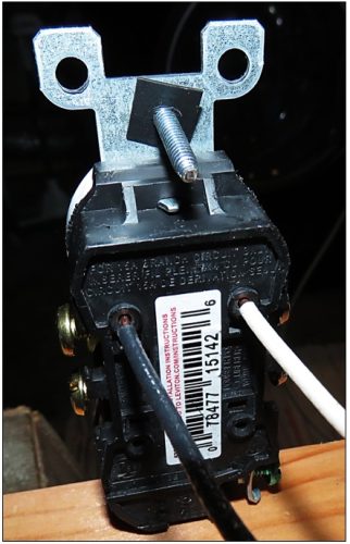
 There are lots of ways to connect wires to Receptacles and Switches. I am not going to deal with all those methods and will only be discussing push-in wire connections, commonly called “bayonet” or “backstab” connections. With these connections the wire is stripped back and pushed into a hole in the back of the receptacle or switch and the wire catches are a sharp metal plate to facilitate contact. It is an inherently small area of connection compared to a wire wrapped around a screw or under a plate. Doing service calls on older installations it was not uncommon to find these connections failed to the point where the wire would fall out of the switch when removing the switch. There would sometimes be signs of overheating and of course the common complaint the light just does not work, or flashes on and off.
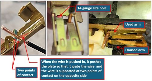
I think when the connections are first made they are pretty adequate, but I am sure as time goes by, these connections become less adequate. Heavy-use circuits or switches would suffer the most. When taking the device apart, these connections seem like they might be adequate as the mechanism that pinches the wire has a circular cut out in the edge that fits the wire and the tension holds the wire against two plates. It is the shape of the arc in the plates that limit backstabs to #14 wire—as well as the load that could be placed on them. That this is not as positive a connection as side screws or wire-nuts is evident with thermal imaging. I suspect over time some of the tension is lost through metal fatigue and that it has no spring memory like spring-steel would have. Once a wire is forced in and then released the plate stays bent as can be seen in the picture below.
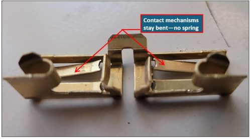
Guts of the backstab mechanism built for two neutrals and two hots at each receptacle of the duplex. Most are not double.
VOLTAGE DROP:
Another issue with these backstab connections is voltage drop. Anyone that has tested for voltage drop of backstabbed receptacles, especially circuits that stab from receptacle to receptacle instead of the better practice of pigtailing the wires and feeding the receptacle from the connections, has likely noticed how one can even tell which way the room was wired by noting the voltage drop. I did a second test where the wires are wire-nutted together with a wire that runs to the receptacle. This eliminated the heating of the receptacles along the run but only changed the voltage drop by about 20%. To keep the voltage drop of the circuit below 5% the maximum number of receptacles on 36′ of wire would be 3 or less. This testing as shown me that one can determine which way the room is wired regardless of whether they are backstabbed or side-wired, as it is the length of the wire and the gauge of the wire that is more important to voltage drop.
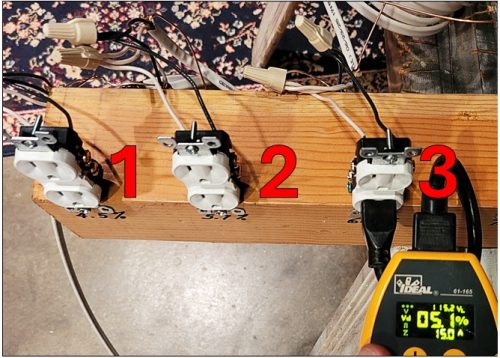
Voltage drop at the 3rd receptacle was about 5.1%
I set up a demonstration of the pigtailing and the results of this testing is below.
Initially I set up a board with 10 receptacles and ran 12′ od 14-2 NM from receptacle to receptacle. The 12′ simulates a representative distance between receptacle one might find in a room/house. Some amount of length is necessary to simulate real world voltage drop conditions. 8 to 12 receptacles on a circuit is common. With this many receptacles on a circuit there is guaranteed to be excessive voltage drop over the length of the whole circuit.
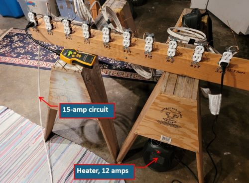
10 Receptacle circuit simulation
Ideally the NEC recommends no more than 3-5% voltage drop over the length of the circuit. It is my opinion, if this is important, it is unlikely any house with #14 receptacle circuits would ever meet the recommendation. When voltage drop gets excessive, appliance operation/efficiency can be affected. The following pictures show the voltage drop on #1 through #10 with a 12 amp load.
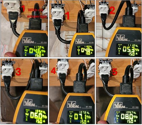
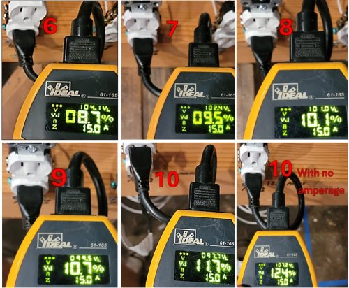
I ran the test under full load for 4 hours, and it was noted receptacles #1 through #9 heated to about 82°F on the face and the back. It should be anticipated that these measurements would be higher with wiring and boxes enclosed in walls with cover plates. The #10 receptacle heated to 114°F on the face and 94°F on the back. This result was almost identical on the pigtailed connections for #10 (1 through 9 did not heat).
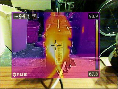
Temperature of the back of the #10 Receptacle after 4 hours
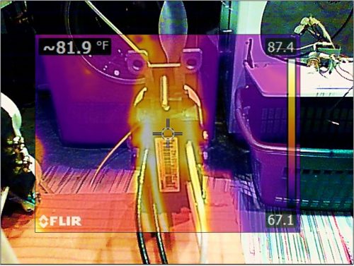
Temperature of the back of the #1 Receptacle after 4 hours
As an aside, one of the more interesting things was how the closely coiled 12′ of wire heated so much more than the wire that was not coiled.
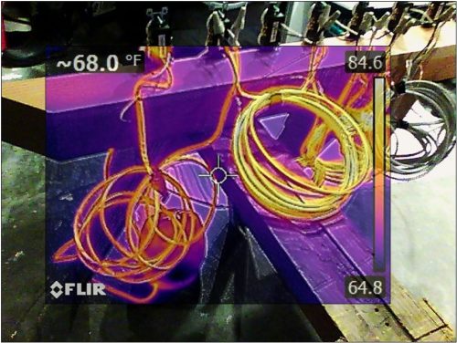
Loosely coiled on the left and tightly coiled on the right
With the heater still on, the voltage at the first receptacle was 118.3 volts and at the last receptacle it measured 110.6 volts. The circuit with no load measured 122.7 volts.
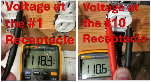
I then pigtailed all the connection, which resulted in no heating of the pigtailed receptacles, as anticipated. I was surprised the voltage drop over the ten receptacles was only reduced by about 20%. I think this voltage drop should be anticipated to get worse as the connections age.
CONCLUSIONS:
If you care about voltage drop, the best solution is to use a bigger wire for your 15 amp circuits. This eliminates backstabbing as they are only allowed on #14 wire devices. Receptacles should still be pigtailed to each receptacle and side screwed (either plate type or wrapped). Pigtailing prevents losing a whole circuit if one receptacle has a problem, even if voltage drop would not be an issue.
How all this would play out with some of the lever connection devices would require further experimentation.
Please share your experience with backstab installations.
Charles Buell Consulting